Dual, or double, water-supply systems are sometimes installed where one of the supplies is either impure, hard, or is otherwise unsatisfactory in quality. Where a supply is too polluted to be fit to drink, it should not be installed in such a situation that it can be used for drinking purposes. The faucets should be locked, or permanently and conspicuously labelled, or placed in inaccessible places. In general, the installation of any polluted water supply is not to be recommended. The principles involved in the installation of dual or multiple water supply systems are no different than for individual supplies. Cross-connections between good and bad water supplies should be avoided.
The rapidity with which water will be delivered to any plumbing fixture is dependent on the available pressure in the city main or from the private pump or storage tank, the number of obstructions in the supply pipe, and the size of the supply pipe. The size of the supply pipe, in turn, is dependent on:
The supply pressure in the street main or from the private pump should be between 30 and 70 lb. per square inch. Information concerning pressure in a public water supply is usually available from the waterworks department. The length of the service or supply pipe, the material of which it is made, the number of turns and fittings, etc. are read from the plans or are determined on the ground. The rate at which water is to be delivered by the pipe should be the sum of the rates of supply to each fixture, with proper allowance for the improbability of the simultaneous use of all of the fixtures. The average daily water consumption is not a factor in the determination of pipe sizes; the maximum rate of demand is the controlling factor. Since the prediction of the maximum rate of demand must be based, to a great extent, on judgment and experience, recommendations based on knowledge and experience will be helpful.
In some cases, because of its greater smoothness and workability, smaller-sized brass pipe is used with satisfaction. It is probable that the capacity of brass pipe is appreciably greater than that of standard wrought pipe. Little can be said, of a definite nature, with regard to the proper size of intermediate pipes, between the service pipe and the branch pipe to the fixture except that the judgment of the designer must be exercised in this determination. His judgment must be based on the knowledge that no pipe should be smaller than the branch to an individual fixture supplied by it, and there would be little purpose in using a branch pipe larger than the service pipe unless the intermediate supply pipe leads from a storage tank.
The first step in the installation of water-supply pipes for city buildings usually consists in the making of the connection to the water main with the lead goose-neck. The laying of the service pipe proceeds simultaneously with this. The installation of the pipes within the building follows. In small buildings the water-supply piping system includes one riser pipe for cold water and one for hot water, and the layout of the piping is simple. In apartment buildings, hotels, large residences, hospitals, etc. there may be a large number of different riser pipes. Under such circumstances simplicity of layout is essential to proper operation and maintenance.
Riser pipes for different purposes may branch from a single distributing manifold in the basement, in some such manner, or fewer and larger riser pipes may be used with more frequent branches to mains and to fixtures. The layout is dependent more on the method of operation and control than on the question of cost, which is approximately the same for either layout. Easy control by the operating engineer or janitor should be the principal consideration.
Each riser pipe should be equipped with a stop-and-waste valve and, if possible, it should be labelled so that the supply to the riser can be cut off without affecting other portions of the building and the manipulation of the wrong valve can be minimized. Pipes branching from the riser main and branches to fixtures should be equipped with valves which are labelled or whose purpose is evident by their location. Valves should be placed in an accessible and visible location.
The bursting of a water pipe is usually followed by such disastrous and costly consequences to property that special care must be taken in pipe installation. Among the causes of failure can be included weak pipe or defective material, an excessive pressure in the pipes, movements of the building, freezing, and water hammer. The danger from high pressure comes as much from the wear on valves and the deterioration of valve gaskets as from the bursting of the pipe. Poor material can be avoided by purchasing material known to fulfil standard specifications. If the material is purchased from reputable dealers and it is guaranteed to equal or better these specifications no trouble need be expected.
The movements of buildings are of such magnitude and have resulted so often in the breakage of plumbing pipes that provision should be made to avoid the damage even in the smallest building. The movements of buildings are due to the settling of the foundation, to wind pressure, to expansion and contraction resulting from temperature changes, and to the drying or moistening of lumber in the structure. No exact measure can be placed on any of these for any building but that the movements are appreciable is attested by every-day experience in frame buildings when the plaster cracks, the floor boards draw away from the base boards, doors will not close, and windows jam.
Measurements in tall buildings show them to be many inches out of plumb in some cases. The Washington monument is known to sway appreciably in the wind, and a famous test on the dome of the Capitol at Washington has shown it to move 6 in. between the hottest and coldest parts of the day. As it is not possible to prevent such movements, the plumber provides for them in the installation of his pipes by the use of expansion joints, the location of the pipes, and in other ways which are discussed in the sections pertaining to the installation of pipes.
Lumber in drying shrinks appreciably, the greater change occurring across rather than along the grain. Lumber will swell and shrink repeatedly as it absorbs moisture and moisture evaporates from it.
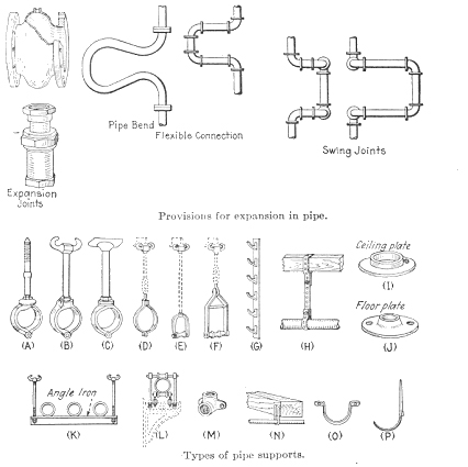 The expansion of water-supply and drainage pipes, particularly hot-water pipes, is sufficient to require attention in design. The movement in a brass hot-water pipe 100 ft. long when the temperature changes from 40 to 212° F. is equal to 0.0000104 X 100X (212 — 40) X 12 -= 2 1/8 in., approximately. It is evident that the movements are appreciable and must be cared for. This can be done by the use of swing joints in threaded pipe or with flexible bends. Supports in which the pipe can move should be used. Many such supports are illustrated below. Expansion joints should be used in hot-water pip- lines at least every 50 ft. and the pipe should be well supported midway between expansion joints. At the expansion joints the pipe should be free to change in length.
| Expansion in cast-iron pipe is usually not provided for because of its relatively low coefficient of expansion and the conditions of its installation. When used as a cold-water supply pipe the changes in temperature are slight and when used as a drainage pipe in a building the normal changes of temperature are within 40 to 50° and the building and pipe are subjected to the same changes in temperature so that the building movements due to temperature changes approximate those of the drainage pipes. The increase in length of 50 ft. of cast-iron pipe with a 50° change of temperature will be about 3/16 in.
In order to minimize movements of drainage pipes due to temperature changes, the discharge of hot wastes into them is usually prohibited. Pipe supportsBreaking of the pipe from movements of the building can be avoided by hanging the pipe in supports which will permit some motion between the pipe and the support. This is possible in all of the supports shown left, except M, which is known as a drop elbow. The pipe is threaded into it ant it is screwed to its support. The pipe should be adequately supported to prevent sagging but it should not be rigidly attached to the building. Since pipe may start vibrating in the supports, some form of soft material, such as felt, should be used to stop the motion or to deaden the sound. |
Lead pipe should be supported for its entire length whenever sagging is possible. Cast-iron and vitrified clay pipe, when laid horizontally or slightly sloping, should be supported at each joint, and wrought, brass, or copper pipe when horizontal, or approximately so, should be supported at least every 10 ft.
Long, vertical lines of pipe are usually supported at each floor, the support being so arranged that the settlement of the building will allow the pipe to lift out of the support. Pipes passing through floors, particularly through concrete floors, should do so through loose sleeves. The pipes should not be encased in the concrete or plaster.
It is desirable to place water-supply pipes so that in case the water is to be shut off the water will drain from the pipes. For this purpose so-called “horizontal” pipe should be placed only approximately horizontal, the slope being towards the stop-and-waste valve or other point of drainage. Where it is not possible to continue the slope in one direction, drain cocks or plugs should be inserted in the line. It is far more desirable, however, to install the entire supply pipe so that it will drain to one point.
In the location of the pipe in the floors, walls, and partitions of a building, the accessibility of the pipe should be considered. It is undesirable to install a pipe so that much damage to the building will result from an attempt to gain access to the pipe. A good plan is to group pipes in “runs” within the walls. These are vertical shafts to which access should be had through doors or easily removed panels.
The shafts should have horizontal partitions at reasonable intervals to prevent the shaft from acting as a chimney in the event of fire. The pipe runs should be lined with waterproof material to prevent moisture from penetrating the walls, and they should be provided with “safe” drains at the bottom to catch leakage or water of condensation which may collect on the colder pipes in humid weather.
Hot-water pipes, cold-water pipes, drainage pipes, gas pipes, electrical conduits, etc. can be grouped in a run. It is undesirable to place hot and cold pipes close together as the temperature of one is likely to affect the temperature of the other. The most objectionable effect will be the heating of the cold-water supply. It is desirable that the outside of the pipe run should be panelled or otherwise covered so as to be easily and inexpensively uncovered and re-covered.
Connections between pipes are made with threaded couplings, threaded unions, flange unions, and calked joints in bell-and spigot pipe. The location of pipe joints and the fitting together of pipes require the exercise of ingenuity in which skill and experience are helpful.
In roughing-in a new piece of work the pipe fitter must be careful that he does not so install the piping that one piece of bell-and-spigot pipe or a fitting must be used to connect two pieces already in place. The remaining piece cannot be connected. Bell ends should be pointed upwards or horizontally and they should be kept away from surrounding obstructions so as to make calking easier.
Joints in threaded pipes are made with couplings. Where two pipes already in position are to be joined the connection is made in any one of three ways: by means of a box union, a, flange union, or a right-and-left threaded pipe coupling. In joining a box or a flange union the method is evident from the figures.
In making a right-hand and left-hand coupling connection the positions of the couplings and pipes. The number of threads cut on the pipes should be just sufficient to make the couplings tight when turned up. Couplings and unions should be used generously inpipe lines to permit taking down portions of the pipe without dismantling the whole system or large portions thereof.
Cleanouts are desirable on pipe lines in order that clogging materials can be removed. They are seldom used on water-supply pipes but are frequently used on drainage pipes. On the former a satisfactory type of cleanout consists of a plugged T, cross, or Y.
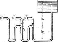 Air binding is caused by the collection of air in the top of loops or inverted traps in a pipe line. The air may accumulate to such an extent that the pressure necessary to force the water over the bends is greater than the available pressure, thus shutting off the flow of water in the pipe. The head of water may sometimes be sufficient to force some water over the loops but the flow will be restricted. The condition which results in air binding is illustrated below. In the condition illustrated in the figure the flow will be stopped if h1 + h2 is materially greater than h3. If h1 + h2 is approximately equal to h3 a small amount of water will flow over the loops and from faucet No. 1 when it is opened, without affecting the existence of the air lock.
Air binding can occur only where there are bends in a pipe line in which air can accumulate and where there is but a small pressure available to force water through the pipes. It will probably occur on the top floor of a building supplied by a roof tank or by a tank on the top floor. Gas or air is more likely to accumulate in top-floor pipes, and the available pressure head to force the water past the stoppage is smallest on the top floor.
Air binding can be prevented by avoiding the installation of inverted traps in the pipe and by the provision of sufficient pressure to overcome the lock if the binding occurs. It can be cured by placing an air valve or a faucet at the top of the inverted trap through which air can escape from the pipe.
Tests of the water-supply pipes should be made after roughing-in and before walls, ceilings, and floors are completed. The tests are made by closing all openings and turning on the water pressure. The pressure maintained during the test should be 50 to 100 per cent higher than the maximum pressure to which it is expected that the system will be subjected.Tests
The increased pressure can be obtained by attaching a hand force pump to the plumbing system and raising the pressure the required amount. The amount of additional water required by the force pump after the pipes are filled is slight, usually less than 5 gal. The force pump should be equipped with a pressure gage. After the required pressure has been reached and the pump has stopped, a drop in the pressure will indicate a leak in the system.
The pipes are then inspected by eye and ear for the leak. A similar procedure is followed after the fixtures have been installed and the plumbing system completed. Tests on the water-supply system are seldom required in plumbing codes but they should be made in the interest of the owner and to assure good work on the part of the contractor.
If you are looking for the best Plumber in Calgary for your services and repairs, please call 24/7 Emergency Services
Fill out the form below and we will get back to you ASAP.
If you have an after-hours emergency, call our 24-hour emergency number at (587) 205-8273 Or email us : general@mrmikesplumbing.ca
Having a Plumbing Emergency?
Quick Links
Quick Links
Contact Us